
 |
Schwabenmax® Serviceseiten |
|
Installation instructions for rigid engine mount Yamaha Vmax 1200. Installation time: approx. 4
hours, depending on your experience. What is needed:
|
| 2. disassembly 2/1Dummy fuel tank,seat front and rear, airbox - rearfender side cover, exhaust Airbox complete (please cover carburettor top) 2/2 Right pillion seat with frame strut, suspension struts, petrol tank 2/3 Completely remove swingarm with rear wheel, do not disassemble. 2/4 Loosen radiator, do not dismantle 2/5 Remove right frame cable/footrests rider right/left 2/7 Loosen engine at all 6 points 2/8 Pull out the front 4 engine mounts with pliers 2/9 Raise the engine with at least 1 tensioning strap at the rear until the engine mounts can be mounted freely. 2/10 Mount the engine mounts with copper paste 2/11 Lower the engine until the rear bolts can be fitted, Tighten these to 2 turns. 2/12 From then on everything backwards as for removal. Finally, tighten all engine bolts as specified in the workshop manual. 3. Release lift motor 3/1 Secure the jack under the oil pan. |
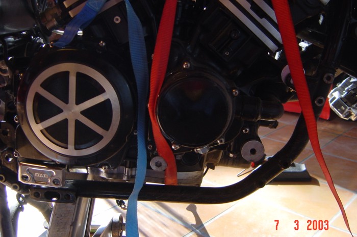 |
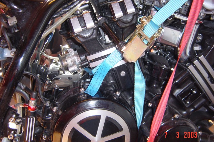
| 3/1 Push the ratchet tensioning straps under the
engine (oil pan) and connect/tension them over the upper frame. |
 |
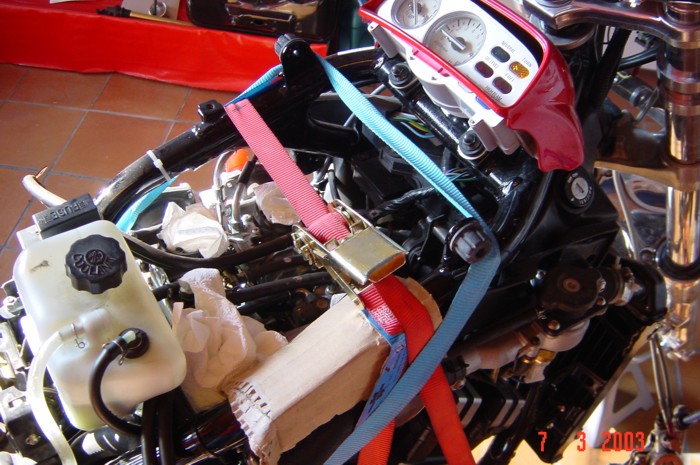 |
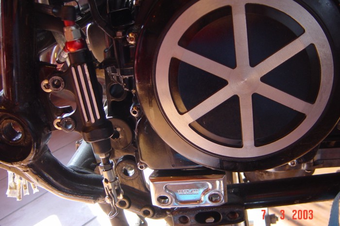
| 3/3 Undo and remove all engine and frame screws. On the top left, remove the aluminium bushing and engine retaining rod to the left! |
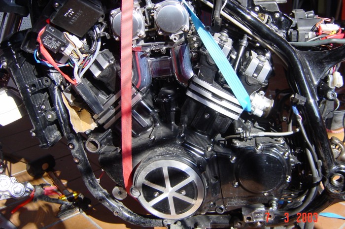 |
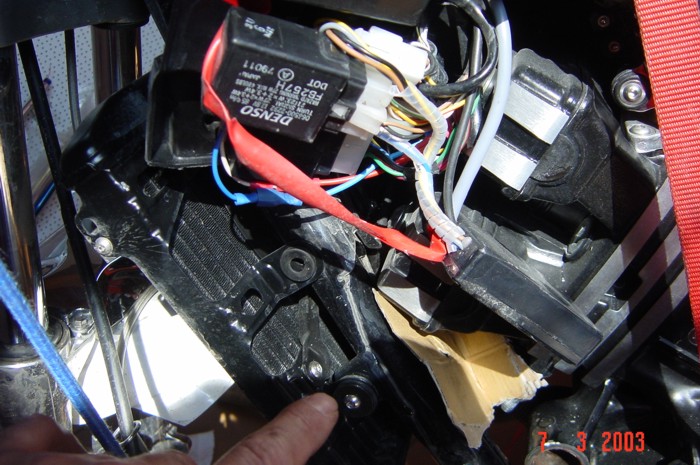
| Press 3/4 engine up gradually with jack and tighten ratchet
straps. Caution: The exhaust manifold bolts are particularly tight in the front frame area. To avoid damage, place a piece of sturdy cardboard or cloth in between, for example. |
 |
 |
 |
|
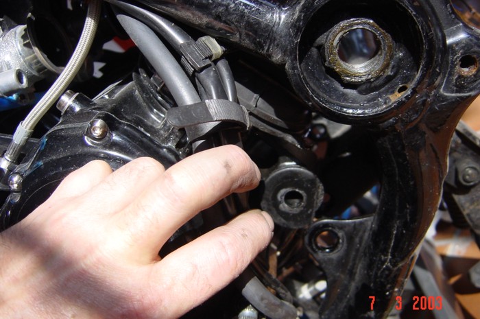
3/5 Pull out the rear rubber engine mounts with pliers
3/6 Coat the aluminium motor bearings with copper paste and press in
|
|
3/7 Slowly lower the engine,
|
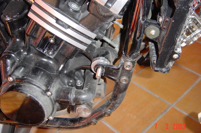
3/8 Mount aluminium frame plates and motor screws, tighten loosely. |
| 3/11 Tighten all motor screws evenly |
| 4 Assemble the remaining parts in reverse order to that described in the disassembly section. |